Update # 4
My apologies for the delay in the Updates, I've been more doing than having time to write about it ;-) The reason for the hurry along was I was invited to be one of the feature cars at the Jumpers & Jazz in July Festival. That meant every weekend and other non-work time was spent getting him ready for the 20th of July. There was much hand wringing and gnashing of teeth in fear it wasn't going to be finished, let alone registered. Would it pass the the RWC (Road Worthy Certificate), inspection???
So this update takes in quite a bit of problem solving and prepping for the Warwick run, and now the Leyburn Sprints run, (the Leyburn organisers saw the Bearcat at Warwick and asked me to be one of the feature vehicles at their turn-out this coming weekend - 17th & 18th August). So, what was done since the last Update on April 16th. It's a long one, so grab your favourite beverage and let's get into it.
After the electricals were sorted out I started on rebuilding the brakes, having never worked on truck brakes, (floating axels) before there was much consulting with Dr Google. Through the Toyota Dyna Face Book group I started corresponding with a gentleman who was an expert on Dyna trucks and very generous with his time and knowledge. I can't thank him enough for his guidance and advice - Thanks Michael, I owe you brother.
During my first under-car inspection after purchasing the Bearcat I noted diff oil dripping off the left hand rear brake backing plate, so started dismantling that one first. The brake shoes and components were soaked in oil and had to be replaced. I checked the other three wheels and although no oil contamination, decided to replace all of the brake shoes. Even though the front ones were passable I thought I'd start afresh. As mentioned previously, my experience with floating axel brakes was nil so it was a steep learning curve. I wanted to know why there was diff oil on the shoes - how did it get that far? After discussions with the Dyna Guru I noted that the outer axel seals were missing on BOTH rear wheels ??? After more investigation and literature searches I found they had been left out. The diff centre had been replaced with one from an Albion truck with a higher ratio - 1.98:1. I had no idea - looking at it from outside it looked totally original. The Albion axel splines are a larger diameter than the original Toyota axels so the OEM seals couldn't be used, and had been left out.
 |
| Brake shoes drenched in differential oil |
 |
Total brake rebuild.
|
Sourcing brakes shoes and brake cylinders & seals was a treasure hunt. I learnt that in the truck industry once a truck gets to a certain age they are just scrapped, and parts are a problem to find. I did finally manage to get a full set of front and rear brake shoes, some seals, and some complete cylinders to replace the ones beyond repair.
 |
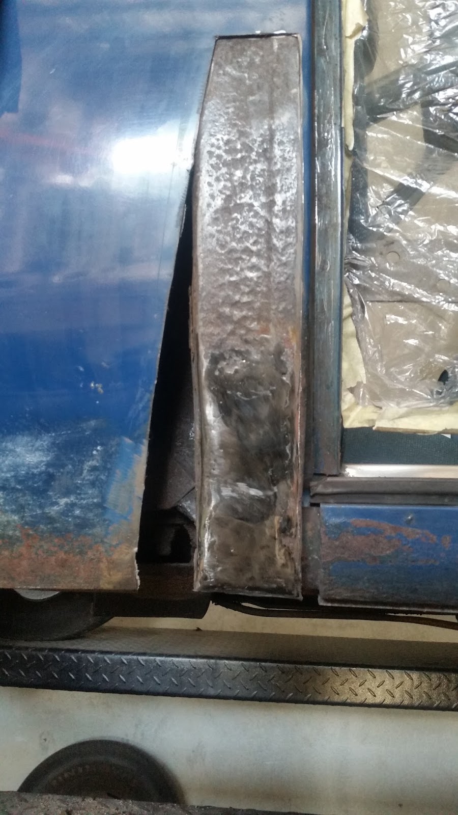
| The left rear brake assembly rebuilt. Note the missing seal at the axel opening. |
Then there was the missing seal problem to be solved. This one caused me some sleepless nights I have to say, but the answer was staring me right in the face the whole time; albeit at a right angle. Because the axel spline was a larger diameter than the axel diameter a normal seal cannot be fitted. I even investigated split seals but could not find any the right size. Then it came to me at my usual 3am waking time... treat it like a steam valve spindle! HA OF COURSE!!! I turned up a packing ring to fit inside the axel tube to give the packing some extra reinforcement, then purchased some 10 mm PTFE valve spindle packing. The added extra with PTFE is that it's self lubricating and handles high temperatures with ease.
 |
| Before wrapping the steering wheel |
 |
| After wrapping. |
I added a spare fuel can that I had lying around the shed, I figured it would get me to the next fuel stop if I really need it it, (10lt), and it looked pretty cool - then realised the exhaust pipe running directly behind it should be insulated!
The RWC inspection went well, the research into what the Main Roads Dept wanted paid off and the Engineer passed it. Getting it registered at the Main Roads Dept was an exercise, but with the most helpful of staff we managed it. Then the insurance, with a some extra terms and conditions it was done!
Patting myself on the back for being nearly ready for the Jumper & Jazz Car Show I took the Bearcat to get a wheel alignment. On the way there was about 10 k of freeway driving. I was a little nervous as I had not had it out of 3rd gear since getting it on the road and didn't want to hold up traffic. I shouldn't have been concerned, changing it into 4th gear it cruised at 100 k (60 mph), at 1000 rpm, and handled pretty well on the road. When I arrived at the the wheel alignment workshop I let it run while I got out, normally something I don't do. It was then I noticed the rumbling water pump bearing - BUGGER !!! I removed the pump as soon as I got home only to find it had suffered some serious damage and repairs in the past. I can only surmise it had been involved in an accident to cause that type of damage. I decided the pump body would not survive in the press to push out the old bearing etc, and pressing in a replacement, so purchased a rebuilt unit out of Oregon USA. I was now sweating on it arriving before I left for Warwick, and it did, arriving on the Tuesday of that week. BUT! The impellors were very different (see photo). I decided to go ahead and fit the rebuilt unit. I had also ordered at the same time a GMC engine workshop manual, which explained that the shorter, opposite rake pump blades were from an earlier model.
 |
| Repaired original pump body. |
 |
| Original repaired impellor. |
 |
| Different impellor blade arrangement |
So all of this lead to this....
The GMC Bearcat in the main street of Warwick Q'LD for the Jumpers & Jazz Festival Car Show.
The next Update will be from the Leyburn Sprints.